

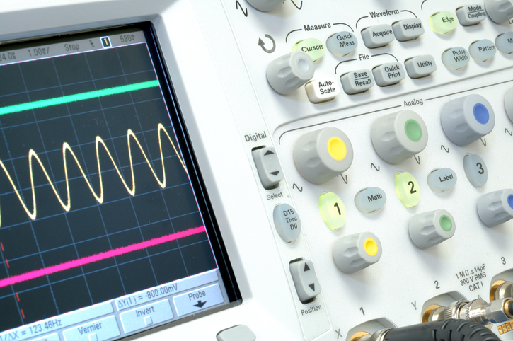
Even simple oscilloscopes are not designed to handle RF challenges as speciallized equipment, the right ONDUINO shield can enhance some of their capabilities...
Purpose:
Monitoring RF signals activity could be for:
- Transmitting profile developpement/characterization
- Amplitude demodulation (ASK/FM modulation)
- Transmitter troubleshooting (Time domain...)
- Check signal presence
- ....
Key Definition:
Signal power is a key parameter for communication transmitters. It refers to the power carried by transmitter signal. Usually, RF power is expressed in "dBm", decibels relative to one milliwatt, and is measured at a defined frequency.
Which ONDUINO to use ?
- Shield reference: RF RANGE
- Functionality: Power Detector - RMS OUTPUT
What about test configuration ?
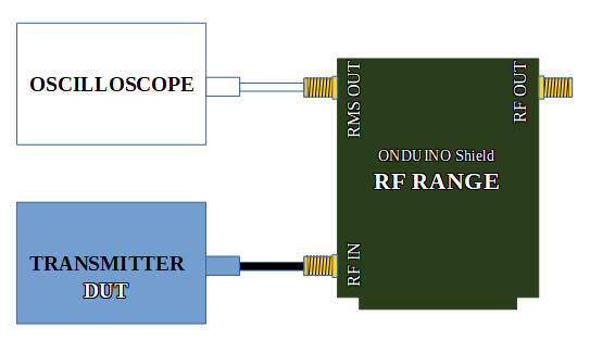
 |
ONDUINO Shield : RF RANGE. |
 |
DUT : Transmitter to monitor its RF activity. |
 |
OSCILLOSCOPE : Used to monitor the signal voltage in time domaine related to RF power seen by shield power sensor, over all allowed frequency band. |
 |
RF Cables : Used for connecting transmitter to concerned ONDUINO Shield. |
Notes :
- DUT stands for Device Under Test
- In case transmitter is equiped with antenna, power could be received in a radiated way using an appropriate antenna in the shiled side too.
How to use it ?
- Plug your shield on one of its compatible Arduino platforms.
- Connect concerned platform to your computer using the appropriate USB cable.
- Download ONDUINO shield Firmware from our website and program your Arduino plateform.
- Download ONDUINO Software from our website and launch it.
- Using ONDUINO Software ( Shield Manual available from conerned menu ), set shield in power detector mode and enable RMS-OUT.
- Connect RMS-OUT to your favorite oscilloscope and start monitoring RF activity in the time domain.
Notes:
- In case of expected RF power exceed maximum shield power input, an external attenuator could be used to lower signal intensity. To read real power, introduced attenuation offset should be settled in calibration Software interface ( Shield Manual available from conerned menu ).